Tuesday 24 April 2018

Published April 24, 2018 by with 0 comment

Matlab for Digital Signal Processing and Processors [Part 1]


Complete Code


clear all
n = [0 : 1 : 10];

x1 = [ones,zeros(1,10)];
subplot(2,4,1)
stem(n,x1,'fill')
title('Impulse')
xlabel('n')
ylabel('Amplitude')

x2 = ones(1,11);
subplot(2,4,2)
stem(n,x2,'fill')
title('Step')
xlabel('n')
ylabel('Amplitude')

x3 = n;
subplot(2,4,3)
stem(n,x3,'fill')
title('Ramp')
xlabel('n')
ylabel('Amplitude')

x4 = (n.*n)./2 ;
subplot(2,4,4)
stem(n,x4,'fill')
title('Parabolic')
xlabel('n')
ylabel('Amplitude')

x5 = [0.5].^n ;
subplot(2,4,5)
stem(n,x5,'fill')
title('Decaying Exponential')
xlabel('n')
ylabel('Amplitude')

x6 = [1.1].^n ;
subplot(2,4,6)
stem(n,x6,'fill')
title('Rising Exponential')
xlabel('n')
ylabel('Amplitude')

x7 = [-0.5].^n;
subplot(2,4,7)
stem(n,x7,'fill')
title('Alternate Decaying Exponential')
xlabel('n')
ylabel('Amplitude')

x8 = [-1.1].^n ;
subplot(2,4,8)
stem(n,x8,'fill')
title('Alternate Rising Exponential')
xlabel('n')
ylabel('Amplitude')


Explanation of the code


clear all
This line of code clears all the variables stored in Matlab Workspace
Before Execution
After Execution


n = [0 : 1 : 10];
Creates an array from '0' to '10' in steps of 1

For eg: If you wanted to create an array from 50 to 100 in steps of 5 it can be done as 
n = [50 : 5 : 100];


Impulse Signal


We have total 11 sample numbers  i.e. n= 0 to n=10 in our array 'n' that we created above.
So according to the formula for impulse signal, the amplitude for Sample at n=0 will be 1.
And the amplitude at the rest of the samples will be zero.

So we will be using the following matlab code to create an impulse signal array -
x1 = [ones,zeros(1,10)]
Here we create an array x1 such that the first number is a one and the rest other numbers are zeros. Matlab has predefined keywords 'ones' and 'zeros' to create arrays of ones and zeros respectively.

For Eg to create an array of ones of length 5 and array of zeros of length 2
ones(1,5)
zeros(1,2)

Both this arrays can be combined as
[ones(1,5),zeros(1,2)]


To create a 2x5 size Matrix of ones and 2x2 size Matrix zeros we use
ones(2,5)
zeros(2,2)

Unit Step Signal


Magnitude is zero for sample number n smaller than zero.
Magnitude is one for sample number greater than or equal to zero.

So we create an array of ones of the same length as that of 'n'


x2=ones(1,11)

Unit Ramp Signal


Magnitude is zero for sample number n smaller than zero.
Magnitude is same as the sample number, when sample number is greater than or equal to zero.

So we create an array that is the copy of 'n'


x3=n


Unit Parabolic Signal


Magnitude is zero for sample number n smaller than zero.
Magnitude is square of the sample number, when sample number is greater than or equal to zero.

So we create an array that is the square of 'n'


x4=n.^2


If you do not use a dot before ^ you'll get an error.
Dot is used for element wise operation. We do not want the square of the array we need the square of its elements.


NEXT : Exponential Signals and Plotting
Read More
      edit

Monday 19 March 2018

Published March 19, 2018 by with 0 comment

[Mini Project] Controlling the temperature of a closed environment (Log 2)

In the previous post I had posted that based on requirement by user that is for either heating or cooling we can switch on/off the heating and cooling element, but this approach seems naive for purpose of achieving a range of temperatures.

So we decided on using a peltier element for heating as well cooling purpose.
By using a peltier element a range of temperatures can be achieved by controlling the amount of current supplied to it!


About peltier device:


Peltier is a semiconductor technology that concentrates the heat on of of its face making the other one cooler. Therefore one of the sides being extremely warm and the other one being extremely cold.
The polarity of the supply decides which face is warm or cool. Reversing the polarity makes the warmer side cool and vice versa.

Peltier Element


The peltier works on a 12 V DC supply but draws a huge current (The peltier we’ll be using in our project draws 3 – 5 A Current). The amount of current it draws decides the magnitude of Heating/Cooling it can provide. Thus the amount of temperature change that we want can be controlled by controlling the amount of current supplied to it.

The efficiency of how cold a side of the peltier gets depends upon how efficiently the other side of the device dissipates the heat. Thus the requirement of a heat sink and a fan to dissipate/spread the  heat on one side and propagate the cold on other side.

HeatSink and Fan Arrangement


Now two major things to be figured out are the feedback loop mechanism to achieve the desired temperature, and the driving circuit for Peltier to control current according to the requirement.


The component list draft :


-Peltier Element
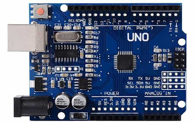
-Arduino Uno

Arduino UNO


-A 2 x 16 LCD to display temperatures current and set

2 x 16 LCD


-Potentiometer for varying the temperature

Potentiometer


-Temperature Sensor DHT11 for measuring current temperature

DHT11 (Temperature and Humidity Sensor)


-x2 Heat sinks and fans
-Thermocol Box as an isolated environment

-Driving circuit components for the peltier current
-Supply for the Peltier Probably an SMPS

Next : Circuit connections and code for LCD Display, DHT11 and Potentiometer with arduino.

Read More
      edit
Published March 19, 2018 by with 1 comment

My Journey to Girnar - A Pilgrimage Site for The Jains


Girnar is a pilgrimage spots for people following Jainism. Located in the Junagadh district of Gujrat, it is known for its religious significance. Not only Jains but the people who worship Lord Shiva and Lord Dattatreya are also fascinated by the pristine atmosphere of Girnar.


According to the holy scriptures of Jainism, Girnar is one of the places where many Jain Tirthankars have attained the liberation of their soul by rigorous penance at the heights of this mountain. Away from the chaos of outside world, the land of salvation is holy and is worshipped by Jains.
There are about 10,000 steps to the summit of Mt. Girnar. At the summit is the shrine of Lord Dattatrey, and the footmarks of Jain Tirthankar Neminath. However, very few Jains visit the summit, since the central temple (Shree Neminath Jain Derasar) is situated at a climb of 4000 Steps.

Entry of temple premises at 4000 steps


The Neminath Jain Temple
There’s another way down the mountain that branches out roughly at 200 steps further from the Jain temple, also known as the Sehsavan Route. The branched route is a little more difficult to manoeuvre through. Generally, the pilgrims prefer to descend from the Sehsavan route since there are three more shrines on the way – The Sehsavan Temple, and the other two shrines dedicated to the milestones that Tirthankar Neminath achieved on his eternal journey to salvation.
I saw a rainbow on my way down!


The Base Village of Mt. Girnar

Junagadh railway station is nearest to Girnar, and a plenty of rickshaws or cabs are available outside the station to reach the base village. The trip from station to base approximately takes 30 mins. The base village a is nothing less than a holy theme park full of monks and ashrams.

Of the many places for accommodation at the mountain bed, the pilgrims generally prefer the ashrams. Hotels are rare to spot but not nil. We had decided to stay in Kuttchi Bhavan (A place of accommodation for people of Kuttchi Community).
An important ritual to be followed by the pilgrims before beginning their ascent is worshipping the base of the berg, also known as Taleti.

Prayers at Taleti

My Experience

My mom was a part of a group of thousand people including the organizers and the monks who travelled from Palitana to Girnar on foot(Padayatra). Their journey was from 21st Feb to 8th March, inclusive of a single day climb at Palitana at the start and a single day climb at Girnar on the last day. So, each day they had to walk 12-15 Km based on the schedule decided by the organizers.
These people stayed in tents for the duration of their yatra. The tents were setup a day or two prior by the workers employed by the organizers, at the places that marked the end of each day’s journey.
The group!
So, me and my dad, along with the family members of the other Padyatris who were a part of this journey assembled with the group at Girnar a day prior to the climb, so that everyone can ascend for prayers at Girnar together.

Started the ascent at 5am, the path till 4000 steps is marked with lights

Early morning view from the top

Uperkot fort and Junagadh Museum are tourist spots that one can visit in Junagadh and are close to Girnar. (Rickshaw’s aren’t allowed inside the Uperkot fort, you’ll either have to walk to explore or hire a taxi inside, the local taxi’s inside the fort don’t allow the rickshaw’s to enter!)
The View from Uperkot fort


Corridors of Uperkot fort


Read More
      edit

Sunday 4 February 2018

Published February 04, 2018 by with 0 comment

[Mini Project] Controlling the temperature of a closed environment (Log 1)


The Objective :

The basic aim of this project is to be able to maintain a constant temperature inside a closed container, the temperature required to be maintained is specified by the user.
The user should be able to set any temperature between those limits , and the project setup will try to maintain the closed system at that set temperature.

Possible Applications :

Temperature control of systems is required by many industries such as food processing, chemical processing etc . 
One of the upcoming application of this system is to replicate favorable climate conditions for the growth a a particular plant. Temperature is one of the factors that comes under climate control.

Initial Approach :

The logic behind working of this project is that a Micro-Controller will poll the readings of a temperature sensor continuously and depending on the set temperature and the current temperature reading provide the necessary instruction to a 'Heating Element' or 'Cooling Element' , thereby completing a feedback loop.

If the Set Temperature < Current Temperature
     Activate Cooling element and Deactivate Heating element
If the Set Temperature > Current Temperature
     Activate Heating element and Deactivate Cooling element

Heating Element can be something like a coil that produces heat when current is passed through it.
Cooling Element can be something like a fan .
Micro-controller is Arduino.
And the closed container can be a Thermocol box


Next : Flaws in the current approach and improvements + fixing some components
Read More
      edit

Thursday 4 January 2018

Published January 04, 2018 by with 0 comment

DSBSC Modulation and Demodulation simulation in Simulink

DSBSC Modulator and Demodulator Block Diagram executed in Simulink

Modulation


Message Signal : 2V(p-p) 200 Hz 
Carrier Signal: 2V(p-p) 1500 Hz

The DSBSC modulation is one type of modulation in which the message is carried on the amplitude of a sinusoidal signal.
Mathematically DSBSC wave can be said to be equal to the product of message and carrier signal.
If Message Signal is
𝑓𝑚(𝑡) =𝑉𝑚 𝑠𝑖𝑛𝜔𝑚𝑡

and Carrier Signal is
𝑓𝑐(𝑡) =𝑉𝑐 𝑠𝑖𝑛𝜔𝑐𝑡

Then their product will be,
𝑓𝑚(𝑡)* 𝑓𝑐(𝑡)=𝑉𝑚 𝑉𝑐 (𝑠𝑖𝑛𝜔𝑚𝑡∗𝑠𝑖𝑛𝜔𝑐𝑡)

Which gives,
𝐹1(𝑡)=𝐴∗[cos((𝜔𝑐−𝜔𝑚)𝑡)−cos((𝜔𝑐+𝜔𝑚)𝑡)]
Modulated Wave

Thus 𝐹(𝑡) can be said to be a DSBSC wave since it has two sideband components 𝜔𝑐−𝜔𝑚 and 𝜔𝑐+𝜔𝑚 .
The product of the two signals is obtained by using a Product-Modulator Circuit.
DSBSC Spectrum


DeModulation

Demodulation of a DSBSC involves a Product-Modulator Circuit followed by a low pass filter. Here the one input to the Modulator is the DSBSC wave and the other input is a signal of unit amplitude which has exactly the same frequency and phase as that of carrier signal.
𝐹2(𝑡)=𝐴∗[cos((𝜔𝑐−𝜔𝑚)𝑡)−cos((𝜔𝑐+𝜔𝑚)𝑡)]∗𝑠𝑖𝑛𝜔𝑐𝑡

Therefore
𝐹2(𝑡)=(𝐴/2)sin((2𝜔𝑐−𝜔𝑚)𝑡)+(𝐴/2)sin((2𝜔𝑐+𝜔𝑚)𝑡)+(𝐴/2)𝑠𝑖𝑛𝜔𝑚𝑡+(𝐴/2)𝑠𝑖𝑛𝜔𝑚𝑡

Reciever Demodulated Wave

The frequencies 2𝜔𝑐−𝜔𝑚 and 2𝜔𝑐+𝜔𝑚 are removed by the low pass filter.
The low pass filter is selected to have pass band edge frequency of twice the frequency of message signal.
Thus the message signal is obtained as
𝐹2(𝑡)=(𝐴/2)𝑠𝑖𝑛𝜔𝑚𝑡+(𝐴/2)𝑠𝑖𝑛𝜔𝑚𝑡

Recovered Message Signal


Here the two terms are obtained from two sidebands each, thus it can be said that transmission of information is possible even with a single sideband!

Conclusion

DSBSC transmits the message signal with two sidebands, thus it consumes less power as compared to DSBFC, However the circuit gets complex.
Its demodulation always requires the availability of the carrier signal in the demodulator. The carrier at the demodulator must have the same frequency and phase of the carrier at the transmitter or some parts of the message signal will be lost.
The generation of the carrier signal at exactly the same frequency and phase of the carrier at the modulation is relatively expensive and may drive the cost of the demodulator to be higher.

The file related to this simulation are availabe on Github 
https://github.com/dhairyagada/DSBSC_Simulink
Read More
      edit

Wednesday 3 January 2018

Published January 03, 2018 by with 0 comment

PIR Sensor Heat Detector

PIR based heat detection 

1. Objective

The objective of this project is to sense heat with the help of infrared radiations emitted by a warm body. Thus it aims at contactless detection of heat

2. Approach


A. Testing the PIR Transducer

The PIR sensor [1] was tested for the nature of output that it gave when a motion was detected. It was observed that the sensor gave a constant voltage at its source terminal when there was no motion in its field of vision. The constant output voltage of the sensor was dependent on the surrounding room temperature.
When a motion of heat source such as human body occurs in the field of vision of the sensor, the output of sensor decreases. The magnitude of decrease in the voltage depends on the amount of heat radiated by the body. The output voltage of the sensor does not return to its constant value until the body has moved out of the field of vision of the sensor.

B. Signal Conditioning (Amplifier)

TSince the output voltage of the PIR sensor is in millivolts, it should be amplified before processing it. An Op-Amp as an inverting amplifier [2] cascaded with an Op-Amp as an inverting buffer is used to amplify the output signal of PIR.

C. Output Logic (Comparator)

The instantaneous value of the signal is compared with the steady value of the signal to know if heat has been detected. If the instantaneous value is lower than the steady value the output becomes high, indicating the presence of a heat source. If the instantaneous value is higher than the steady value, which occurs in the presence of cold objects the output remains low indicating that there is no potential heat source around.

D. Output (LED)

The output is indicated with the help of a led, which glows when heat is detected.

E. Calibration

Since the steady value of the sensor system depends on the surrounding temperature, the value with which the instantaneous signal is compared needs to be calibrated.The calibration is done with the help of a potentiometer.

3. EDA Tools Used

The EDA tools used by us were KiCad and FreeRouting.
Kicad is an open source EDA tool which was used by us to design the schematic and layout of the PCB.
Freerouting is the tool which was used by us to auto-route the PCB tracks.

4. Schematics


i. PIR Sensor

ii. Amplification stage

iii. Comparator stage and final output

Complete Schematic

5. PCB Layout


6. Conclusions

The implemented circuit thus detects a heat source in its field of vision successfully, without establishing any physical contact with the source
Objects that are at room temperature or colder do not affect the output.
The main component of this project is a PIR sensor, the sensor is said to be a passive sensor because it does not emit energy of any type but merely accepts incoming radiations.
The system of the project is dependent on the surrounding temperature, and it needs to be calibrated before using. Thus there lies a scope of improvement in this project to make it independent of the surrounding conditions.

7. Applications

A. Human Motion Detection

The circuit can successfully detect the presence of a human body around it due the heat emitted by human body.
Thus it can act as an intrusion alarm. The advantage of this circuit is that it can even function in a darker environment.
Another application of human detection using this circuit is its implementation in home automation such as light switching.
An advanced application of this circuit can be a human tracking system based on PIR sensor network and video [3]

B. Overheating detection of a system

This circuit can be used as a safety mechanism inside a system to detect if it overheats, by calibrating the detector to the normal operating temperature of the system.
The overheating would cause the detector’s output to become high which can in interrupt the normal processing of the system and initialize a predefined procedure to cool down the system.
Thus the PIR based heat detector can be used as a part of a feedback network of a system.
It can also be used as an alarm for protection of a heat sensitive system to indicate the presence of an unwanted heat source nearby.

C. Remote temperature measurement

The circuit can be modified to indicate the temperature difference of a remote object related to its surrounding, by measuring the change in amplitude that it causes in the steady value of the PIR sensor.
Read More
      edit