In the previous post I had posted that based on requirement by user that is for either heating or cooling we can switch on/off the heating and cooling element, but this approach seems naive for purpose of achieving a range of temperatures.
So we decided on using a peltier element for heating as well cooling purpose.
By using a peltier element a range of temperatures can be achieved by controlling the amount of current supplied to it!
Peltier is a semiconductor technology that concentrates the heat on of of its face making the other one cooler. Therefore one of the sides being extremely warm and the other one being extremely cold.
The polarity of the supply decides which face is warm or cool. Reversing the polarity makes the warmer side cool and vice versa.
The peltier works on a 12 V DC supply but draws a huge current (The peltier we’ll be using in our project draws 3 – 5 A Current). The amount of current it draws decides the magnitude of Heating/Cooling it can provide. Thus the amount of temperature change that we want can be controlled by controlling the amount of current supplied to it.
The efficiency of how cold a side of the peltier gets depends upon how efficiently the other side of the device dissipates the heat. Thus the requirement of a heat sink and a fan to dissipate/spread the heat on one side and propagate the cold on other side.
Now two major things to be figured out are the feedback loop mechanism to achieve the desired temperature, and the driving circuit for Peltier to control current according to the requirement.
-Peltier Element
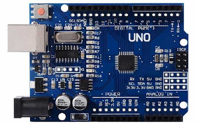
-Arduino Uno
-A 2 x 16 LCD to display temperatures current and set
-Potentiometer for varying the temperature
-Temperature Sensor DHT11 for measuring current temperature
-x2 Heat sinks and fans
-Thermocol Box as an isolated environment
-Driving circuit components for the peltier current
-Supply for the Peltier Probably an SMPS
Next : Circuit connections and code for LCD Display, DHT11 and Potentiometer with arduino.
So we decided on using a peltier element for heating as well cooling purpose.
By using a peltier element a range of temperatures can be achieved by controlling the amount of current supplied to it!
About peltier device:
The polarity of the supply decides which face is warm or cool. Reversing the polarity makes the warmer side cool and vice versa.
 |
| Peltier Element |
The peltier works on a 12 V DC supply but draws a huge current (The peltier we’ll be using in our project draws 3 – 5 A Current). The amount of current it draws decides the magnitude of Heating/Cooling it can provide. Thus the amount of temperature change that we want can be controlled by controlling the amount of current supplied to it.
The efficiency of how cold a side of the peltier gets depends upon how efficiently the other side of the device dissipates the heat. Thus the requirement of a heat sink and a fan to dissipate/spread the heat on one side and propagate the cold on other side.
 |
| HeatSink and Fan Arrangement |
Now two major things to be figured out are the feedback loop mechanism to achieve the desired temperature, and the driving circuit for Peltier to control current according to the requirement.
The component list draft :
-Arduino Uno
 |
| Arduino UNO |
-A 2 x 16 LCD to display temperatures current and set
 |
| 2 x 16 LCD |
-Potentiometer for varying the temperature
 |
| Potentiometer |
-Temperature Sensor DHT11 for measuring current temperature
 |
| DHT11 (Temperature and Humidity Sensor) |
-x2 Heat sinks and fans
-Thermocol Box as an isolated environment
-Driving circuit components for the peltier current
-Supply for the Peltier Probably an SMPS
Next : Circuit connections and code for LCD Display, DHT11 and Potentiometer with arduino.


